
Please note, the steps below can only be carried out by a suitably qualified technician and ONLY when given explicit written authority by Fox to check/replace fuse(s). If battery cases are opened without prior approval, this may invalidate the warranty.
- Checking battery cell stack voltage.
- Charging the cell stack – be careful here as different ECS/EQ models have different numbers of cells in series.
- Checking continuity of the fuse inside the battery module.
Here is a guide (including photos) showing where to attach the multimeter probes and charger crocodile clips for:
LV5200
- Please power down the battery and disconnect all cables and DC supplies from the battery.
- The top of the battery case will have to be removed by undoing the 6 T10 screws. Then the lid may be taken off.
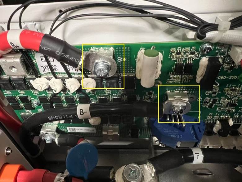
- The two cables from the cell stack can be seen running up the far left corner to the BMS PCB. It is at this point that the cell stack voltage is measured as shown below.
- This is also the charge point for the cell stack. Only charge the battery when it is switched off and not connected to any inverter.
- For recharge: Set the bench charger to 52VDC and set the current to c.2 amps. After some 30 minutes the charge current may be set to a full 5 amps. The bench supply will enter constant current mode and the voltage screen will indicate the battery voltage so you will know when the target voltage is reached. There might be a small spark as the crocodile clips are attached to the cell stack charge points.
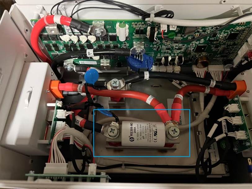
- The 200A fuse can be seen in the picture below.
- The two bolts holding the fuse in is where continuity needs to be checked. Sometimes these fuses only partially fail so be aware of this. The fuse resistance is written on the fuse itself. In this case it will be c. 1.4mohms, but many DVM’s will just read 0 ohm.
- Replace the fuse as required with a 200A fuse supplied by FoxESS.
- Reassemble and test voltage and operation.
LV52
- Please power down the battery and disconnect all cables and DC supplies from the battery.
- The top of the battery case will have to be removed by undoing the 6 T10 screws. Then the lid may be taken off.
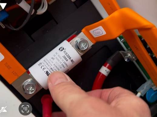
- The two cables from the cell stack can be seen running up to fuse and the negative terminates at the orange covered busbar on the PCB as shown below:
- It is at this point that the cell stack voltage is measured as shown below.
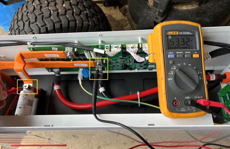
- This is also the charge point for the cell stack. Only charge the battery when it is switched off and not connected to any inverter.
- For recharge: Set the bench charger to 52VDC and set the current to c.2 amps. After some 30 minutes the charge current may be set to a full 5 amps. The bench supply will enter constant current mode and the voltage screen will indicate the battery voltage so you will know when the target voltage is reached. There might be a small spark as the crocodile clips are attached to the cell stack charge points.
- Replace the fuse as required with a 200A fuse supplied by FoxESS.
- Reassemble and test voltage and operation.
ECS/EQ batteries
There are two types of ECS/EQ battery. One is the master and one is the slave. The master is at the top of the stack and has the DC switch and SOC LEDs mounted in it.
Please be aware that different ECS models have different cell architecture so when having to perform a local recharge this MUST be taken into account or irreversible cell damage may result.
Charging voltages:
ECS2900: 56VDC maximum
ECS4100: 56VDC maximum
ECS4300: 56VDC maximum
ECS4800: 44VDC maximum
Set the bench supply to the above voltages and set the charge current to 2A in constant current mode. This will allow an element of cell balancing during charging. The bench supply voltage will display the actual stack voltage.
The slave is easiest to check so this will be described first:
Slave:
- Please power down the battery and disconnect all cables and DC supplies from the battery.
- Remove the slave battery in question from the stack.
- Turn the battery module upside down insert the DC jumper plug to complete the DC circuit.
- Cell stack voltage may now be measured at the connector pins on the top of the battery.
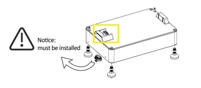
- Measure the battery voltage at the following points of the cell stack shown below in the master photo.
- The fuse will have to be disconnected at one end and a continuity check will have to be done. In this case it will be c. 1.4mohms, but many DVM’s will just read 0 ohm.
- Replace the fuse as required with an 80A fuse supplied by FoxESS.
- Reassemble and test voltage and operation.
Master:
- Please power down the battery and disconnect all cables and DC supplies from the battery.
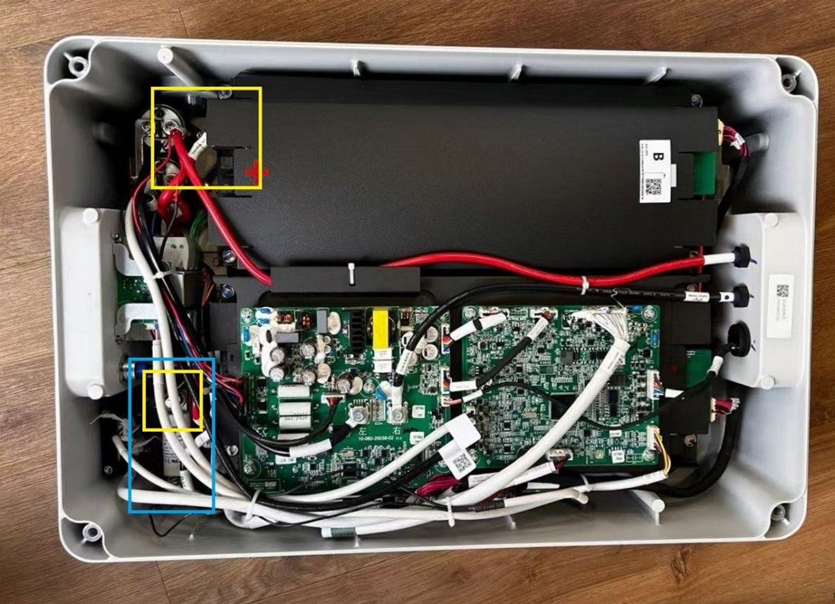
- Turn the battery module upside down and use a 13mm deep socket and extension bar to remove the 4 bolts keeping the item sealed and remove the bottom cover.
- Measure the battery voltage at the following points of the cell stack shown below in yellow – +ve terminal is under the black plastic tab. -ve terminal is on the fuse.
- The fuse (in blue) will have to be disconnected at one end and a continuity check will have to be done. In this case it will be c. 1.4mohms, but many DVM’s will just read 0 ohm.
- Replace the fuse as required with an 80A fuse supplied by FoxESS.
- Reassemble and test voltage and operation.
EP5, EP11 series
- Please power down the battery and disconnect all cables and DC supplies from the battery.
- Remove from the wall mount and place on a sturdy flat surface with the torx bolts facing upwards.
- Remove the torx bolts (T25) and carefully remove the side panel. These will shear easily so please show diligence when using a ‘rattle-gun’.
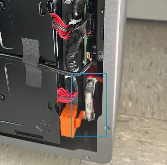
- The 50A/70A fuse will be seen in the lower right corner of the enclosure.
- Disconnect the non-live end of the fuse with a screwdriver to undo the cable attached to it and measure the resistance. It should read 0 ohms. Any other reading warrants replacement.
- Replace the fuse as required with a 50/70A fuse supplied by FoxESS.
- Reassemble and test voltage and operation.
Test points:
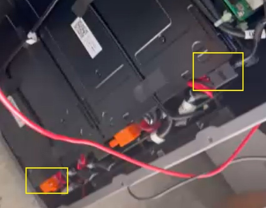
Voltage should measure in the region of 198 VDC for the EP5 and 396VDC for the EP11. Test points are under the black tabs of insulating plastic. Positive to red, negative to black.
Please take due diligence when measuring these high DC voltages as they may be lethal.
Fuse location:
MIRA HV25, HV2600 series
- Please power down the battery and disconnect all cables and DC supplies from the battery.
- Dismantle the battery stack to gain access to the battery/batteries required.
- There are a series of T10 and T20 screws that will need removing. 8* T20 either side of the battery at the front holding the chrome rack handles and the rest are T10 screws located along the top rear, sides and top front of the enclosure.
- Carefully remove the top panel/lid and the two cell stacks and fuse location will be seen:
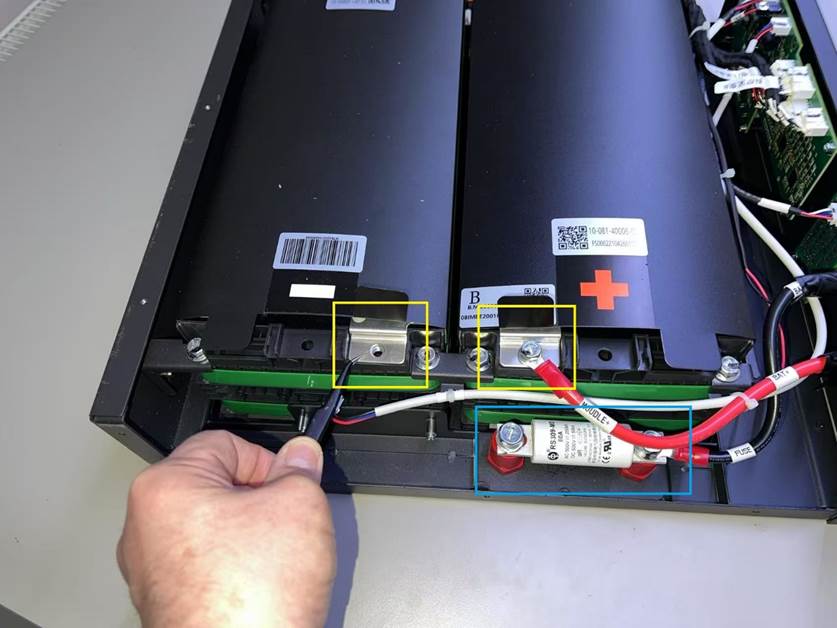
- Measure the battery voltage at the following points of the cell stack shown below.
- The fuse will have to be disconnected at one end and a continuity check will have to be done. In this case it will be c. 1.4mohms, but many DVM’s will just read 0 ohm.
- Replace the fuse as required with an 80A fuse supplied by FoxESS
- Reassemble and test voltage and operation.


